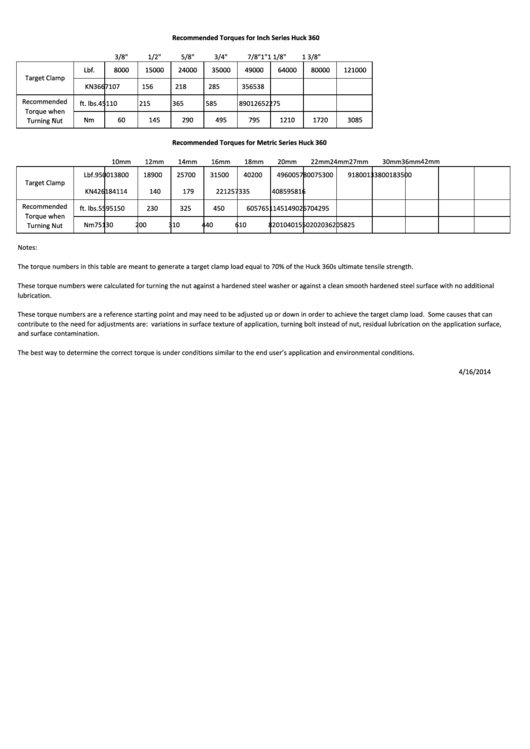
Huck 360 Torque Chart (Inches)
ADVERTISEMENT
Recommended Torques for Inch Series Huck 360
3/8"
1/2"
5/8"
3/4"
7/8"
1"
1 1/8"
1 3/8"
Lbf
Lbf.
8000
8000
15000
15000
24000
24000
35000
35000
49000
49000
64000
64000
80000
80000
121000
121000
Target Clamp
KN
36
67
107
156
218
285
356
538
Recommended
ft. lbs.
45
110
215
365
585
890
1265
2275
Torque when
Nm
Nm
60
60
145
145
290
290
495
495
795
795
1210
1210
1720
1720
3085
3085
T
Turning Nut
i
N t
Recommended Torques for Metric Series Huck 360
42mm
10mm
12mm
14mm
16mm
18mm
20mm
22mm
24mm
27mm
30mm
36mm
Lbf.
9500
13800
18900
25700
31500
40200
49600
57800
75300
91800
133800
183500
Target Clamp
KN
42
61
84
114
140
179
221
257
335
408
595
816
Recommended
ft. lbs.
55
95
150
230
325
450
605
765
1145
1490
2670
4295
T
Torque when
h
Nm
75
130
200
310
440
610
820
1040
1550
2020
3620
5825
Turning Nut
Notes:
The torque numbers in this table are meant to generate a target clamp load equal to 70% of the Huck 360s ultimate tensile strength.
These torque numbers were calculated for turning the nut against a hardened steel washer or against a clean smooth hardened steel surface with no additional
lubrication.
These torque numbers are a reference starting point and may need to be adjusted up or down in order to achieve the target clamp load. Some causes that can
contribute to the need for adjustments are: variations in surface texture of application, turning bolt instead of nut, residual lubrication on the application surface,
and surface contamination.
The best way to determine the correct torque is under conditions similar to the end user’s application and environmental conditions.
4/16/2014
ADVERTISEMENT
0 votes
Related Articles
Related forms
Related Categories
Parent category: Life
 1
1


