Microwave Transmision Lines
ADVERTISEMENT
UNIT- 1 : MICROWAVE TRANSMISION LINES - LECTURE 7
NUMERICALS ON SMITH CHART (IMPEDANCE CALCULATION) :
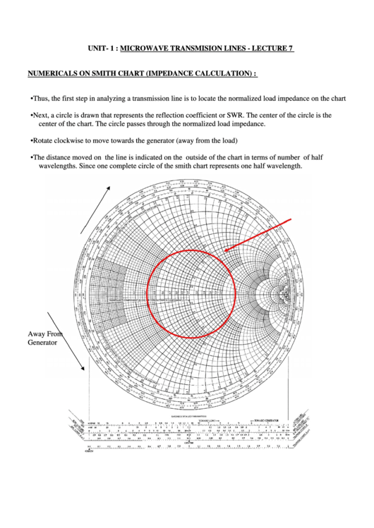
• Thus, the first step in analyzing a transmission line is to locate the normalized load impedance on the chart
• Next, a circle is drawn that represents the reflection coefficient or SWR. The center of the circle is the
center of the chart. The circle passes through the normalized load impedance.
• Rotate clockwise to move towards the generator (away from the load)
• The distance moved on the line is indicated on the outside of the chart in terms of number of half
wavelengths. Since one complete circle of the smith chart represents one half wavelength.
Away From
Generator
ADVERTISEMENT
0 votes
Related Articles
Related forms
Related Categories
Parent category: Education
 1
1


