ANNEX M
AWS D1.1/D1.1M:2010
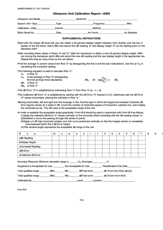
Ultrasonic Unit Calibration Report—AWS
Ultrasonic Unit Model ___________________________
Serial No. _____________________________________
Search Unit—Size______________
Type ________________________
Frequency________________ MHz
Calibration—Date ______________
Interval ______________________
Method ______________________
Block Serial No.________________
Data ____________________ As Found ___________________ As Adjusted
SUPPLEMENTAL INSTRUCTIONS
• Start with the lowest dB level that you can obtain a 40 percent display height indication from directly over the two in
section of the DS block. Add 6 dBs and record this dB reading “a” and display height “b” as the starting point on the
tabulation chart.
• After recording these values in Rows “a” and “b,” slide the transducer to obtain a new 40 percent display height. With-
out moving the transducer add 6 dBs and record the new dB reading and the new display height in the appropriate row.
Repeat this step as many times as the unit allows.
• Find the average % screen values from Row “b” by disregarding the first 3 and the last 3 tabulations. Use this as %
in
2
calculating the corrected reading.
• The following equation is used to calculate Row “c”:
%
is Row “b”
1
%
is the average of Row “b” disregarding
2
%
⎛
⎞
2
×
-------
the first and last three tabulations.
dB
=
20
log
+
dB
⎝
⎠
2
1
%
1
dB
is Row “a”
1
dB
is Row “c”
2
• The dB Error “d” is established by subtracting Row “c” from Row “a”: (a – c = d).
• The Collective dB Error “e” is established by starting with the dB Error “d” nearest to 0.0, collectively add the dB Error
“d” values horizontally, placing the subtotals in Row “e.”
• Moving horizontally, left and right from the Average % line, find the span in which the largest and smallest Collective dB
Error figures remain at or below 2 dB. Count the number of horizontal spaces of movement, subtract one, and multiply
the remainder by six. This dB value is the acceptable range of the unit.
• In order to establish the acceptable range graphically, Form M-8 should be used in conjunction with Form M-9 as follows:
(1) Apply the collective dB Error “e” values vertically on the horizontal offset coinciding with the dB reading values “a.”
(2) Establish a curve line passing through this series of points.
(3) Apply a 2 dB high horizontal window over this curve positioned vertically so that the longest section is completely
encompassed within the 2 dB Error height.
(4) This window length represents the acceptable dB range of the unit.
Row
Number
1
2
3
4
5
6
7
8
9
10
11
12
13
a
dB Reading
b
Display Height
c
Corrected Reading
d
dB Error
e
Collective dB Error
Accuracy Required: Minimum allowable range is ______ .
%
(Average)___________ %
2
Equipment is: Acceptable for Use _________ Not Acceptable for Use _________ Recalibration Due Date__________
Total qualified range _______ dB to _______ dB = _______ dB
Total error _______ dB (From the Chart above)
Total qualified range _______ dB to _______ dB = _______ dB
Total error _______ dB (From Form M-9)
Calibrated by __________________________________
Level _______
Location ________________________
Form M-8
344
 1
1


