Aircraft Accident Brief Ntsb/aab-02/01 (Pb2002-910401): Egypt Air Flight 990, Boeing 767-366er, Su-Gap - National Transportation Safety Board Page 18
ADVERTISEMENT
: Egypt Air Flight 990, Boeing 767-366er, Su-Gap - National Transportation Safety Board Printable pdf") 1
1  2
2  3
3  4
4  5
5  6
6  7
7  8
8  9
9  10
10  11
11  12
12  13
13  14
14  15
15 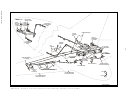 16
16 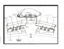 17
17  18
18  19
19 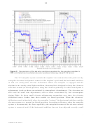 20
20  21
21  22
22  23
23  24
24  25
25  26
26  27
27  28
28  29
29  30
30  31
31  32
32  33
33  34
34  35
35  36
36  37
37  38
38 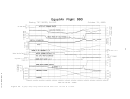 39
39  40
40  41
41  42
42  43
43  44
44  45
45 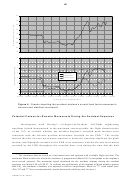 46
46  47
47  48
48  49
49  50
50  51
51  52
52  53
53  54
54  55
55  56
56  57
57  58
58  59
59  60
60  61
61  62
62  63
63  64
64  65
65  66
66  67
67  68
68  69
69  70
70  71
71  72
72  73
73  74
74  75
75  76
76  77
77  78
78  79
79  80
80  81
81  82
82  83
83  84
84  85
85  86
86  87
87  88
88  89
89  90
90  91
91  92
92  93
93  94
94  95
95  96
96  97
97  98
98  99
99  100
100  101
101  102
102  103
103  104
104  105
105  106
106  107
107  108
108  109
109  110
110  111
111  112
112  113
113  114
114  115
115  116
116  117
117  118
118  119
119  120
120  121
121  122
122  123
123  124
124  125
125  126
126  127
127  128
128  129
129  130
130  131
131  132
132  133
133  134
134  135
135  136
136  137
137  138
138  139
139  140
140  141
141  142
142  143
143  144
144  145
145  146
146  147
147  148
148  149
149  150
150  151
151  152
152  153
153  154
154  155
155  156
156  157
157  158
158  159
159  160
160 12
After control cable movement is translated to input control rod movement, the
control rods move control valves inside the PCAs, allowing high-pressure hydraulic fluid
to flow to one side or the other of the actuators’ pistons (depending on the direction of the
input), resulting in elevator movements that correspond to the direction of the input. When
the elevators reach the commanded position, feedback linkages move the control valves to
a position in which the hydraulic fluid is blocked off, resulting in no further movement of
the actuator piston or elevator.
Testing, evaluation, and analysis of the 767 elevator system showed that any
movement of the control columns (whether pilot-induced or not) would have resulted in
concurrent, identifiable movements of the elevators, which would have been recorded on
the FDR.
An elevator feel-and-centering unit transmits hydraulic and mechanical feel forces
to hold the elevator at the neutral (trimmed) position when no control column force is
applied. It also provides feedback (or feel) force to the control column that increases as the
control column is moved forward or aft. The feel forces provided are essentially equal at
both pilot positions because of the connections between the left and right elevator systems.
The captain’s and first officer’s control columns have authority to command full
travel of the elevators under most flight conditions and normally work together as one
system. However, the two sides of the system can be commanded independently because
of override mechanisms at the control columns and aft quadrant. Therefore, if one side of
the system becomes immobilized, control column inputs on the operational side can cause
full travel of the nonfailed elevator. In addition, in many cases, control column inputs on
the operational side can also result in nearly full travel of the elevator on the failed side
through the override mechanisms. The elevator PCAs are installed with compressible
links located between each bellcrank assembly and PCA input control rod to provide a
means of isolating a jammed PCA, thus allowing the pilots to retain control of that
elevator surface through its two remaining (unjammed) PCAs.
767 Elevator Blowdown Information
During ground operations, the 767 elevator PCAs can drive the elevators through a
range of motion from 28.5° in the nose-up direction to 20.5° in the nose-down direction.
However, in-flight elevator deflections can be limited by the aerodynamic forces acting on
the elevator. The maximum position to which the elevator can move is that which balances
the aerodynamic forces that are acting on the elevator surfaces against the force produced
by the elevator PCAs and is referred to as its “blowdown” position. Thus, as the airplane’s
airspeed increases (increasing the aerodynamic forces acting against the elevator PCAs),
the elevators’ range of motion is increasingly limited.
The maximum output force produced by the elevator PCAs is generated by the
hydraulic system pressure acting on the PCAs’ piston area; if all three elevator PCAs are
working properly, the total output force for each elevator surface is the sum of the forces
30
produced by all three of that elevator’s PCAs. When a dual elevator PCA failure occurs,
NTSB/AAB-02/01
ADVERTISEMENT
0 votes
Related Articles
Related forms
 Investigation Party Form")


 During An Allegiant Air Flight")


Related Categories
Parent category: Legal