"Positive Displacement Reciprocating Pump Fundamentals - Power And Direct Acting Types" By Herbert H. Tackett, Jr., James A. Cripe, Gary Dyson Page 12
ADVERTISEMENT
 1
1 2
2 3
3 4
4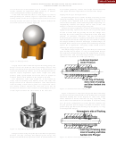 5
5 6
6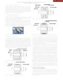 7
7 8
8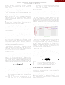 9
9 10
10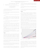 11
11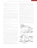 12
12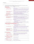 13
13 14
14Table of Contents
56
PROCEEDINGS OF THE TWENTY-FOURTH INTERNATIONAL PUMP USERS SYMPOSIUM • 2008
1. Reduce pump speed
allows all fluid cylinder pumping chambers to become fully primed.
a. Increase the plunger or piston size within a given model and
A bypass line with a shut-off valve should be installed in discharge
stroke length.
piping between pump and check valve back to suction supply
b. For a given stroke length, increase the quantity of plungers or
source, not into the pump suction line to prevent flow discontinuity.
pistons, i.e., use a triplex pump instead of a duplex, or a quintuplex
Install a discharge check valve beyond the bypass connection to
instead of a triplex, etc.
protect pump from discharge system pressure during pump idle
c. Change to a larger (longer) stroke length pump.
periods and pump startup.
Discharges piping “dead ends” are to be avoided or provided
with dampening device. This type of feature can be responsible for
2. Change the type of suction valve used. Lightweight valves
generally require less NPSHR due to the reduction in valve
undesirable piping harmonics and can contribute to elevated levels
of vibration and noise.
cracking pressure.
For some services the natural pump pressure or flow fluctuations
may not be appropriate. In these cases it is prudent to use a
3. If reduced pump speed is possible and changing valve type is
pulsation dampener for the installation. For maximum effectiveness
not, NPSHR could potentially be reduced by using a light (less
the dampener should be mounted adjacent to the pump fluid
spring force) suction valve spring, or if pump operating is slow
enough, no suction valve spring at all.
cylinder. Recommendations for dampener size and type can be
obtained from dampener manufacturers based on details of pump
type and size, service conditions, and piping system.
Ultimately, using a booster pump to provide ample NPSH should
Install flanges or unions as close to the pump as practical to
be considered if the system constraints dictate. Such a pump
should be installed adjacent to suction supply vessel, have an
allow for fluid cylinder removal during maintenance.
Shut-off valves are required in both suction and discharge lines
NPSHR less than total suction system NPSHA, and have a
discharge head at least 20 percent greater than positive displacement
to isolate pump when maintenance is required. They should be of
reciprocating pump NPSHR + pipe friction losses + acceleration
full opening design, such as a gate valve.
head. A suction pulsation dampener or stabilizer adjacent to the
When connecting two or more pumps to a common suction
positive displacement reciprocating pump suction connection is
and/or discharge line exercise care to prevent a mutually reinforcing
also appropriate to protect the booster pump from the pulsating
pressure wave from occurring during operation. This can be
fluid mass inertia of the positive displacement reciprocating pump.
achieved by adding the capacities of all pumps that will operate
simultaneously to determine line velocities for sizing pipe and
Pump Discharge Piping System
calculating the acceleration head. The best way to avoid a mutually
reinforcing pressure wave is to install independent suction and
Listed below are the fundamental requirements for a discharge
discharge lines to each pump.
piping system.
Figure 31 gives an example of the recommendations outlined in
Piping should not be smaller than pump discharge connection,
the previous section for an appropriate pump piping system, while
and should:
Figure 32 provides an example an inappropriate pump piping
•
Be as short and direct as possible.
system configuration.
•
Be one to two sizes larger than pump discharge connection with
increasers used at pump.
•
Contain a minimum number of turns. Accomplish any necessary
turns with long radius elbows or laterals.
•
Have a fluid velocity not exceeding three times maximum
suction line fluid velocity shown in Figure 29 for pump crankshaft
operating speed.
•
Be provided with gauge and drain connections adjacent to pump.
All positive displacement reciprocating pumps deliver fluid and
build pressure until action is taken to control and stabilize the
pump’s work or a failure occurs. To protect pump, piping, and
personnel from hazards associated with operating a “positive
displacement” pump against a “dead head” a safety relief valve
Figure 31. Piping System Appropriate Design.
should always be provided between the pump and discharge valve.
The safety relief valve should be sized to pass the entire pump
capacity and the cracking pressure should be set at 10 percent over
the specified working discharge pressure and have an accumulation
pressure not exceeding 110 percent of cracking pressure.
The safety relief valve outlet connection should ideally be piped
back to the suction supply vessel. Piping back to the suction pipe
can cause discontinuities in the suction pipe flow that can result in
poor pump operation and damage. Should it become necessary
to pipe the safety relief valve back to the suction piping, the
connection into the suction pipe should be a minimum of 10
suction pipe diameters in length back toward the suction supply
vessel away from the pump suction connection. This will allow any
flow discontinuity created by the relief valve flow into the suction
pipe to be smoothed out by time and viscous effect.
A discharge bypass line from pump discharge piping back to the
suction supply vessel permits lubrication to reach critical pump and
Figure 32. Piping System Inappropriate Design.
drive parts during startup without subjecting them to high loads and
ADVERTISEMENT
0 votes
Related Articles
Related forms
 By John H Hopkins Jr. Sheet Music")
 By John H Hopkins Jr. Sheet Music")
 By John H Hopkins Jr. Sheet Music")

 Designation Of Patient Advocate Form And Directions For Durable Power Of Attorney For Health Care Form
Medical
Designation Of Patient Advocate Form And Directions For Durable Power Of Attorney For Health Care Form
Medical
 Form 232 - Power Of Attorney By Individual For The Collection Of A Specified Check Drawn On The United States Treasury - 1975
Legal
Form 232 - Power Of Attorney By Individual For The Collection Of A Specified Check Drawn On The United States Treasury - 1975
Legal

 Form R-1012 - Application For Exemption And Direct Payment Authorization For A Call Center As Defined Under Louisiana Revised Statute - Sales Tax Division Of Department Of Revenue Of State Of Louisiana
Financial
Form R-1012 - Application For Exemption And Direct Payment Authorization For A Call Center As Defined Under Louisiana Revised Statute - Sales Tax Division Of Department Of Revenue Of State Of Louisiana
Financial


Related Categories
Parent category: Business