"Positive Displacement Reciprocating Pump Fundamentals - Power And Direct Acting Types" By Herbert H. Tackett, Jr., James A. Cripe, Gary Dyson Page 4
ADVERTISEMENT
 1
1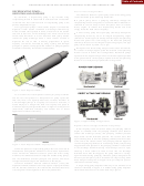 2
2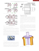 3
3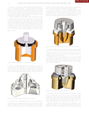 4
4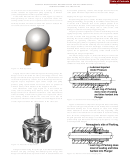 5
5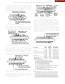 6
6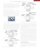 7
7 8
8 9
9 10
10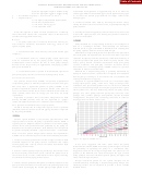 11
11 12
12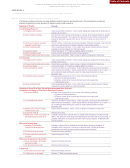 13
13 14
14Table of Contents
48
PROCEEDINGS OF THE TWENTY-FOURTH INTERNATIONAL PUMP USERS SYMPOSIUM • 2008
This valve is primarily used for higher pressure applications,
percent by volume. Well suited for application pump speeds up to
up to 10,000 psig (690 barg); it is best suited for clean fluids.
API-674 (1995) and Hydraulic Institute speed limitations.
However, it can tolerate some suspended solids in the pumped
The design in Figure 11 uses an elastomer/polymer disc
fluid. Particulates up to 45 micron and in concentrations not to
guided by a stem (bolt or stud with wear sleeve) at the center as
exceed 1 percent by volume can be accommodated. This valve is
it opens and closes. There are two seating surfaces on both the
well suited for application pump speeds up to API-674 (1995)
valve and valve seat, one at the disc’s outer edge and one toward
and Hydraulic Institute speed limitations.
the center near the guide stem, which creates a tight seal.
As with the standard wing guided valve, the design in Figure
9, also has wings to guide it as it opens and closes; the seating
surfaces between the valve and valve seat are again beveled.
However, this design has an elastomer/polymer insert imbedded
into the valve head that conforms around trapped solids to create
a tight seal when the valve returns to the valve seat. The valve is
suitable for fluids containing particulates up to 45 micron and
in concentrations not to exceed 3 percent by volume with a
20 to 25 percent pump speed reduction of API-674 (1995)
Table 1 limits.
Figure 11. Disc Type Valve Center Guided Abrasion Resistant.
This design is primarily used for low to moderate pressure appli-
cations, up to 4000 psig (276 barg) and is best suited for fluids
containing solids up to 45 micron and in concentrations not to
exceed 3 percent by volume with a 20 to 25 percent pump speed
reduction of API-674 (1995) limits.
The double ported disc valve design, Figure 12, is also a metal
disc guided by a stem/cage at the center as it opens and closes.
There are two seating surfaces on both the valve and valve seat, one
at the disc’s outer edge and one toward the center near the guide
Figure 9. Wing Guided Valve Abrasion Resistant.
stem to create a tight seal.
The disc valve design, Figure 10, consists of a metal disc
guided by a stem (bolt or stud with wear sleeve) at the center as
it opens and closes. There are two seating surfaces on the valve
and valve seat, one at the disc’s outer edge and one toward the
center near the guide stem. These surfaces create a tight seal.
Figure 12. Disc Type Valve Double Ported.
The unique feature of this design is that it allows flow around
the outside diameter of the valve, as with all the other single
ported valve designs previously presented, and also permits flow
Figure 10. Disc Type Valve Standard Center Guided.
through the center of the valve near the guide stem. Hence the
name “double ported.” This additional flow area at the disc’s
This valve type is primarily used for low to moderate pressure
center permits higher flow rates for the same valve size.
applications, up to 4000 psig (276 barg) and is best suited for clean
Primarily used for low to moderate pressure applications, up to
fluids. The design can tolerate some suspended solids in the pump
3000 psig (207 barg), it is best suited for clean fluids. However, this
product, up to 25 micron and in concentrations not to exceed 1
design can tolerate some suspended solids in the pump product up
ADVERTISEMENT
0 votes
Related Articles
Related forms
 By John H Hopkins Jr. Sheet Music")
 By John H Hopkins Jr. Sheet Music")
 By John H Hopkins Jr. Sheet Music")

 Designation Of Patient Advocate Form And Directions For Durable Power Of Attorney For Health Care Form
Medical
Designation Of Patient Advocate Form And Directions For Durable Power Of Attorney For Health Care Form
Medical
 Form 232 - Power Of Attorney By Individual For The Collection Of A Specified Check Drawn On The United States Treasury - 1975
Legal
Form 232 - Power Of Attorney By Individual For The Collection Of A Specified Check Drawn On The United States Treasury - 1975
Legal

 Form R-1012 - Application For Exemption And Direct Payment Authorization For A Call Center As Defined Under Louisiana Revised Statute - Sales Tax Division Of Department Of Revenue Of State Of Louisiana
Financial
Form R-1012 - Application For Exemption And Direct Payment Authorization For A Call Center As Defined Under Louisiana Revised Statute - Sales Tax Division Of Department Of Revenue Of State Of Louisiana
Financial


Related Categories
Parent category: Business