Laboratory Exercise Basic Electrical Calculations
ADVERTISEMENT
 1
1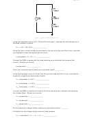 2
2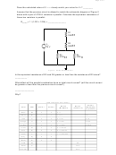 3
3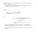 4
4Page 1 of 4
Team Members: ______________________________
______________________________
______________________________
ENGR 199 – Introduction to Engineering Principles and Practices I – Fall 2009
Laboratory Exercise
Basic Electrical Calculations and Measurements
Students successfully completing this lab exercise will accomplish the following
Objective:
objectives:
1. Gain familiarity reading resistor color codes.
2. Learn how to construct simple resistive circuits.
3. Gain familiarity with basic electrical calculations.
4. Learn how to measure resistance, voltage and current using a Digital
Multimeter (DMM)
Digital Multimeter, various fixed resistors, breadboard, power supply
Equipment:
Procedure:
1.
Resistance Identification and Measurement
Obtain three resistors and sort them as R1, R2, and R3. Using the table of resistor color
codes shown at the end of this document, determine the nominal resistance of each
resistor from its color bands. Measure the actual resistance using the DMM as an
ohmmeter.
Using the formula below, calculate the percent error between the measured value and the
nominal value of each resistor. From the percent error calculation, determine whether or
not the resistor is within tolerance. Record all resistor information in table 1.
%
100 %
Table 1: Resistor identification and measurements
Within
Color Code
Color Code
Measured
#
Color Code
% error
Tolerance?
Resistance
Tolerance
Resistance
(Y or N)
R1
R2
R3
2.
Circuit Assembly and Measurement
Construct the voltage divider circuit shown in the schematic diagram of Figure 1 below.
Measure the source voltage (V
) to be approximately 10 V before applying it to the circuit.
IN
Record your measured source voltage.
V
(measured) = _______________
IN
ADVERTISEMENT
0 votes
Related Articles
Related forms


Related Categories
Parent category: Education