Field Plotting Using Teledeltos Paper Page 3
ADVERTISEMENT
 1
1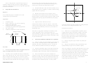 2
2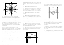 3
3 4
43.2
Plot the potential along the line AB, between the tip
4.
Parallel Plate Electrodes with Tube
Equipotentials
of the sharp electrode and the flat electrode. In your log
book draw a graph of potential versus distance along the
4.1
Take a piece of Teledeltos paper 150 mm on a side.
line.
Paint two straight parallel electrodes 120 mm long and
about 100 mm apart, and a hollow circular electrode of
3.3
Measure the resistance as best you can
10cm
3.4
Now add paint to make the tip of the electrode 15
A
A'
mm radius. Repeat the potential plot along the line AB.
Flow
lines
How do the potential plots compare? Why the difference?
4cm
3cm
3.5
Measure the resistance again. Again compare.
B'
B
Comment
3.6
Measure the resistance between the electrodes.
2.7
Count the number of 'squares' parallel to the
Make a cut in the Teledeltos sheet about 20 mm long and
equipotentials and the number parallel to the flow lines
parallel to the current flow. Measure the resistance. Has it
1
2
altered? Why, or why not?
(this will be the number of equipotentials plus one). The
curvilinear net can be 'transformed' (in the minds eye) to a
about 3cm outer radius as shown.
3.7
Make a slit across the current flow and remeasure the
rectangular net with the same number of squares in each
resistance. Compare with the previous measurement and
direction as the curved set. Since the resistance of each
4.2
Set the supply voltage to 5V, and measure the
comment on differences of similarities.
square is independent of its size the resistance of the
potential difference between electrode 1 and points along
rectangular set is the same as that of the original. Since you
the line BB'. Repeat for the line AA' and plot graphs of
3.8
Make a conducting paint strip about 30 mm long
know the resistance of a square you can estimate the
both sets of results, using error bars to indicate
resistance of the array of squares. Compare this with the
parallel to the current flow. Again measure the resistance
uncertainties.
measured value.
and compare with the previous results.
4.3 From the p.d. graphs determine values for the electric
3.9
Do you expect a conducting paint strip across the
There is an extensive mathematical theory of such
field component E
along the lines, and sketch graphs for
x
direction of current flow to alter the resistance? Check
conformal transformations arising from theory of complex
both of them.
your prediction.
numbers. You may be allowed to enjoy this in later years.
4.4
From the results of 4.2 determine E
midway along
x
2.8
Keep the results not only to write up a report but also
AA', estimating the uncertainty in this result.
to compare with the results of a computer simulation to be
made in a later experiment.
Electrodes
3.
Field Near a Sharp Electrode
B
A
3.1
Take a new infinite sheet about 150 mm square.
Paint an electrode along one edge and make this the earth
electrode. Make the opposite edge with an electrode
protruding 50 mm inwards, about 15 mm wide and with a
tip of radius 5 mm.
3
Teledeltos WTN/CGP 20/10/94
ADVERTISEMENT
0 votes
Related Articles
Related forms


")


Related Categories
Parent category: Education