Research Of Trajectory Design Error Of Coil Piling Of Geodesic Winding Page 3
ADVERTISEMENT
 1
1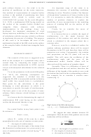 2
2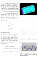 3
3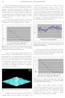 4
4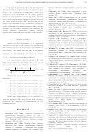 5
5 6
6RESEARCH OF TRAJECTORY DESIGN ERROR OF COIL PILING OF GEODESIC WINDING
147
The modeling process of winding includes
several stages. Phase trajectory modeling is the
first. Therefore, at this stage, the error should be
less than 0.5%. At 36 polyhedron, the dihedral
angle between the normals of two adjacent FE is
10 degrees and the length error should be less than
0.2%, which satisfies the accuracy of modelling
stage.
Thirdly, we examine the nature of the error
.
Let us consider two pairs of adjacent finite
elements {(ABC); (ADB)} and {(ABC); (ACE)},
through which the wind is going (fig. 2). Element
Fig. 3. RM wind laying modeling on the cylinder in Ansys
(ADB) is rotated clockwise relating the (ABC),
therefore, it introduces an error with the "+" and
Each wind is modelled with reinforcement
the element (ACE) is rotated counter-clockwise
angles at the starting point of 30, 45, 70, 85
relating to the (ABC), therefore, if introduces an
degrees.
Large
initial
reinforcement
angles
error with the sign "-".
experimentally demonstrated the greatest error of
the mathematical model of wind laying
.
For each cylinder different models of FE
partitioning provided by the package Ansys were
chosen. Among the main characteristics of the
partition we can identify "fineness of the partition"
and "partition type." Experiment was conducted on
the "fineness of the partition" in the range from 0.6
cm to 0.05 cm, and various types of partitions:
Smart-sized, Mapped, Sized. The lower boundary
of
fineness
partitioning
is
caused
by
its
unreasonable calculating resource taking. At each
Fig. 2. Adjacent finite elements
point of the wind the program stores the data on
the value of the angle of reinforcement, which are
Since the wind has a cyclic trajectory, we
compared with the theoretical ones.
can assume that the wind laying error
passing i-
Based on the data the graphs of the error of
th element has equally probable, both the rising
the mathematical model of the
fineness
and descending characters. Probability of changing
partitioning are obtained. For example, for the
the angle is determined by the direction of
fineness of the partition of the cylinder 0.3 cm long
reinforcement wind and design of finite-element
and 36cm radius of 10 cm, the starting point of 24
partitioning. Hence, during the change of the
will get the chart in figure 4.
mathematical model error
has alternating
character in case of winding the surface of
complex bodies.
RESULTS OF RESEARCH
To test this model (in the Ansys) numerical
experiment
was
performed.
Cylinders
with
diameters of 10, 20 cm and a length of 36 cm and
180 cm were selected as the wound surfaces. The
starting points are arbitrary points on the left edge
of the cylinder, the end points are the points at the
Fig. 4. Graph of error size dependence on the point RM wind
right edge of the cylinder. Figure 3 shows the
trajectory on the cylinder (for
error percentage of the
example of one of the wind’s modelling.
reinforcement angle is taken).
ADVERTISEMENT
0 votes
Related Articles
Related forms


")


Related Categories
Parent category: Education