Rebound Hammer Test Worksheet Page 2
ADVERTISEMENT
 1
1 2
2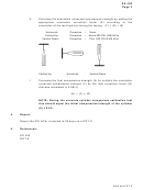 3
3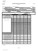 4
4SD 409
Page 2
(2)
Perform the test hammer procedure on the cylinder as per 3.3B
through 3.3H.
(3)
Perform the compressive strength test on the cylinder
according to SD 420 and record the cylinder compressive
strength (A).
(4)
Compare the compressive strength of the cylinder (A) to the
orientation corrected compressive strength (F) determined by
the test hammer in 3.2B(2). Calculate the field correction factor
(G) = (A) / (F).
(5)
When possible, apply this correction factor to field tests of the
same concrete according to 3.3I.
3.3
Field tests.
A.
Operate the test hammer in a horizontal position, whenever feasible.
B.
If the concrete surface is rough, grind points to be tested with the
carborundum stone.
C.
Press the test hammer plunger at exactly right angles to the surface of
the concrete being tested. Press the plunger slowly and uniformly until
released. Do not jerk or try to anticipate the plunger release.
D.
After impact, press the lock button and read the rebound value shown
on the rider. Record the reading.
E.
Take a minimum of 15 rebound readings. Take only one reading at a
given point. Very high readings may be caused by rock or steel near
the surface at the point of impact, and very low readings may be
caused by trapped air pockets near the surface at the point of impact.
F.
Discard the highest reading, the lowest reading, and any that are
obviously in error. Calculate the sum of the remaining readings (B) and
the average of the remaining readings (C).
G.
Convert the average of remaining reading (C) to compressive strength
(D) in PSI (kPa) by using the Central Lab calibration chart for that
particular test hammer. (Do not use the calibration curves on the test
hammer.)
mso.mat 9-14
ADVERTISEMENT
0 votes
Related Articles
Related forms


Related Categories
Parent category: Business