Physics 1bl Electric Potentials And Fields Page 4
ADVERTISEMENT
 1
1 2
2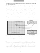 3
3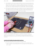 4
4 5
5 6
6Physics 1BL
Electric Potentials & Fields
Summer Session II 2010
A7. The multimeter will measure the potential difference between the point probed on the
paper and the negative terminal of the power supply (which is also the potential of the
negative silver ink conductor). To measure this potential difference at a given point,
gently press the red probe against the black Teledeltos paper without puncturing the
paper. The value of electric potential at a given point can be read from the multimeter.
A8. Check that the multimeter agrees with the readout on the power supply by looking at
the voltage between the metal pushpins. Check that you have good conduction and
good contact around your silver conducting path by touching a multimeter probe to
each conductor. You should still see the 10V from the supply.
This picture shows the power supply, set at 10 V, connected to the two silver ink
conductors. In this setup the outer conductor is connected to the negative of the power
supply and is assumed to be at 0 V. The multimeter is reading the potential difference
between the outer conductor and a point on the teledeltos paper about midway between the
conductors.
Activity B: Finding Equipotential Surfaces
B1. Find three equipotential contours using the following method:
a) Select the voltages for the equipotential you will draw. Choose equally spaced
integer voltages covering the range from 0V to the voltage level of the output of the
power supply.
4
ADVERTISEMENT
0 votes
Related Articles
Related forms


 Supplemental Ohio Corporation Franchise Tax Schedules And Instructions For Electric Companies And Combined Electric Companies Tax Year 2004
Financial
Supplemental Ohio Corporation Franchise Tax Schedules And Instructions For Electric Companies And Combined Electric Companies Tax Year 2004
Financial
 Form 50-154 - Electric Company And Electrical Cooperative Rendition Of Taxable Property - 1999
Financial
Form 50-154 - Electric Company And Electrical Cooperative Rendition Of Taxable Property - 1999
Financial
 Form 50-154 - Electric Company And Electrical Cooperative Rendition Of Taxable Property - 2005
Financial
Form 50-154 - Electric Company And Electrical Cooperative Rendition Of Taxable Property - 2005
Financial


Related Categories
Parent category: Education