Hexagon Socket Set Screws, Flat Type/hexagon Bolts Size Chart
ADVERTISEMENT
[Technical Data]
[Technical Data]
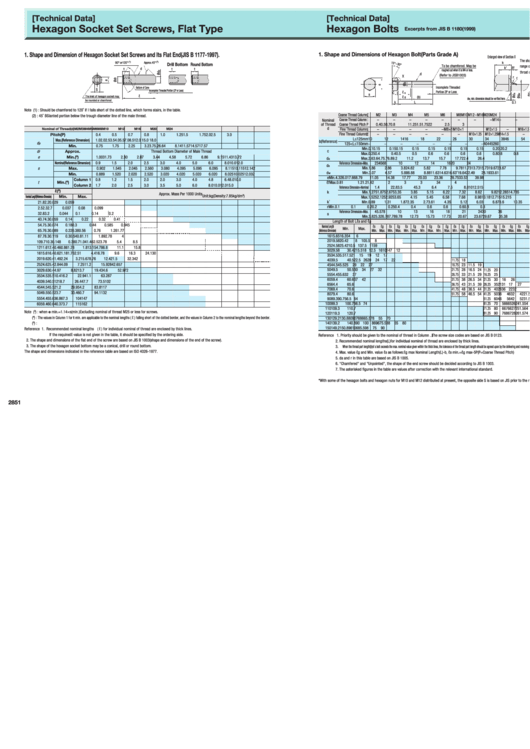
Hexagon Socket Set Screws, Flat Type
Hexagon Bolts
Excerpts from JIS B 1180(1999)
1. Shape and Dimension of Hexagon Socket Set Screws and Its Flat End(JIS B 1177-1997).
1. Shape and Dimensions of Hexagon Bolt(Parts Grade A)
Enlarged view of Section X
The shaded area indicates the
90°
or120°
(
1
)
Approx.45°
(
2
)
k
Drill Bottom Round Bottom
To be chamfered. May be
range of the max. and min.
k'
ℓf
t
d
t
t
roughed out when it is M4 or less.
throat dimension of a fillet weld.
d
(Refer to JISB1003)
X
r r
Incomplete Threaded
Bottom of Cone
S
Incomplete Threaded Portion (2P or Less)
Portion 2P or Less
ℓ
C
s
s
ℓ
The inlet of hexagon socket may
ℓ
(b)
g
dw, min. dimension should be verified here.
be rounded or chamfered
k
L
0.1
Unit:mm
Note (1) : Should be chamfered to 120˚ if l falls short of the dotted line, which forms stairs, in the table.
Coarse Thread Column
M2
M3
M4
M5
M6
M8
M10
M12
−
M16
M20
M24
(2) : 45˚ BSlanted portion below the trough diameter line of the male thread.
Coarse Thread Column
−
−
−
−
−
−
−
−
M14
−
−
−
Nominal
of Thread
Coarse Thread Pitch P
0.4
0.5
0.7
0.8
1
1.25
1.5
1.75
2
2
2.5
3
d
Nominal of Thread(d)
M2
M3
M4
M5
M6
M8
M10
M12
M16
M20
M24
Fine Thread Column
−
−
−
−
−
M8×1
M10×1
M12×1.5
−
M16×1.5
M20×1.5
M24×2
Fine Thread Column
−
−
−
−
−
−
M10×1.25 M12×1.25 M14×1.5
−
M20×2
−
Pitch(P)
0.4
0.5
0.7
0.8
1.0
1.25
1.5
1.75
2.0
2.5
3.0
L≤125mm
10
12
14
16
18
22
26
30
34
38
46
54
Max.(Reference Dimension)
1.0
2.0
2.5
3.5
4.0
5.5
7.0
8.5
12.0
15.0
18.0
b(Reference)
d
p
125<L≤150mm
−
−
−
−
−
−
−
−
40
44
52
60
Min.
0.75
1.75
2.25
3.2
3.7
5.2
6.64
8.14
11.57
14.57
17.57
Min.
0.1
0.15
0.15
0.15
0.15
0.15
0.15
0.15
0.15
0.2
0.2
0.2
d
Approx.
c
Thread Bottom Diameter of Male Thread
f
Max.
0.25
0.4
0.4
0.5
0.5
0.6
0.6
0.6
0.6
0.8
0.8
0.8
e
Min.(
)
3
1.003
1.73
2.30
2.87
3.44
4.58
5.72
6.86
9.15
11.43
13.72
d
Max.
2.6
3.6
4.7
5.7
6.8
9.2
11.2
13.7
15.7
17.7
22.4
26.4
a
Nominal(Reference Dimension)
0.9
1.5
2.0
2.5
3.0
4.0
5.0
6.0
8.0
10.0
12.0
Reference Dimension=Max.
2
3
4
5
6
8
10
12
14
16
20
24
d
s
Min.
1.86
2.86
3.82
4.82
5.82
7.78
9.78
11.73
13.73
15.73
19.67
23.67
s
Max.
0.902
1.545
2.045
2.560
3.080
4.095
5.095
6.095
8.115
10.115
12.142
d
Min.
3.07
4.57
5.88
6.88
8.88
11.63
14.63
16.63
*
19.64
22.49
28.19
33.61
Min.
0.889
1.520
2.020
2.520
3.020
4.020
5.020
6.020
8.025
10.025
12.032
w
e
Min.
4.32
6.01
7.66
8.79
11.05
14.38
17.77
20.03
23.36
26.75
33.53
39.98
Column 1
0.8
1.2
1.5
2.0
2.0
3.0
4.0
4.8
6.4
8.0
10.0
Min.(
)
t
4
ℓf
Max.
0.8
1
1.2
1.2
1.4
2
2
3
3
3
4
4
Column 2
1.7
2.0
2.5
3.0
3.5
5.0
6.0
8.0
10.0
12.0
15.0
Reference Dimension=Nominal
1.4
2
2.8
3.5
4
5.3
6.4
7.5
8.8
10
12.5
15
ℓ(
)
5
k
Min.
1.275
1.875
2.675
3.35
3.85
5.15
6.22
7.32
8.62
9.82
12.285
14.785
Approx. Mass Per 1000 Units
Unit:kg(Density:7.85kg/dm
)
Nomi n al L ength(Reference D i m ensi o n)
Min.
Max.
3
Max.
1.525
2.125
2.925
3.65
4.15
5.45
6.58
7.68
8.98
10.18
12.715
15.215
k '
Min.
0.89
1.31
1.87
2.35
2.7
3.61
4.35
5.12
6.03
6.87
8.6
10.35
2
1.8
2.2
0.029
0.059
r
Min.
0.1
0.1
0.2
0.2
0.25
0.4
0.4
0.6
0.6
0.6
0.8
0.8
2.5
2.3
2.7
0.037
0.08
0.099
Reference Dimension=Max.
4
5.5
7
8
10
13
16
18
21
24
30
36
3
2.8
3.2
0.044
0.1
0.14
0.2
s
Min.
3.82
5.32
6.78
7.78
9.78
12.73
15.73
17.73
20.67
23.67
29.67
35.38
4
3.7
4.3
0.059
0.14
0.22
0.32
0.41
Length of Bolt L
ℓs and ℓg
5
4.7
5.3
0.074
0.18
0.3
0.44
0.585
0.945
Nominal Length
ℓs
ℓg
ℓs
ℓg
ℓs
ℓg
ℓs
ℓg
ℓs
ℓg
ℓs
ℓg
ℓs
ℓg
ℓs
ℓg
ℓs
ℓg
ℓs
ℓg
ℓs
ℓg
ℓs
ℓg
Min.
Max.
6
5.7
6.3
0.089
0.22
0.38
0.76
1.26
1.77
(Reference Dimension)
Min.
Max.
Min.
Max.
Min.
Max.
Min.
Max.
Min.
Max.
Min.
Max.
Min.
Max.
Min.
Max.
Min.
Max.
Min.
Max.
Min.
Max.
Min.
Max.
0.56
2.78
16
15.65
16.35
4
6
8
7.7
8.3
0.119
0.3
0.54
0.8
1.11
1.89
4
20
19.58
20.42
8 10
5.5
8
10
9.7
10.3
0.148
0.38
0.7
1.04
1.46
2.52
3.78
5.4
8.5
25
24.58
25.42
10.5 13
7.5 11
5
9
12
11.6
12.4
0.46
0.86
1.28
1.81
3.15
4.78
6.8
11.1
15.8
30
29.58
30.42
15.5 18 12.5 16 10 14
7 12
16
15.6
16.4
0.62
1.18
1.76
2.51
4.41
6.78
9.6
16.3
24.1
30
35
34.5
35.5
17.5 21 15 19 12 17
20
19.6
20.4
1.49
2.24
3.21
5.67
8.76
12.4
21.5
32.3
42
40
39.5
40.5
22.5 26 20 24 17 22 11.75 18
25
24.6
25.4
2.84
4.09
7.25
11.2
15.9
28
42.6
57
45
44.5
45.5
25 29 22 27 16.75 23 11.5 19
30
29.6
30.4
4.97
8.82
13.7
19.4
34.6
52.9
72
50
49.5
50.5
30 34 27 32 21.75 28 16.5 24 11.25 20
55
54.4
55.6
32 37 26.75 33 21.5 29 16.25 25
35
34.5
35.5
10.4
16.2
22.9
41.1
63.2
87
60
59.4
60.6
37 42 31.75 38 26.5 34 21.25 30 16
26
40
39.5
40.5
12
18.7
26.4
47.7
73.5
102
65
64.4
65.6
36.75 43 31.5 39 26.25 35 21
31 17
27
45
44.5
45.5
21.2
29.9
54.2
83.8
117
70
69.4
70.6
41.75 48 36.5 44 31.25 40 26
36 22
32
50
49.5
50.5
23.7
33.4
60.7
94.1
132
80
79.4
80.6
51.75 58 46.5 54 41.25 50 36
46 32
42 21.5 34
55
54.4
55.6
36.8
67.3
104
147
90
89.3
90.7
56.5 64 51.25 60 46
56 42
52 31.5 44 21 36
66.5 74 61.25 70 56
60
59.4
60.6
40.3
73.7
115
162
100
99.3
100.7
66 52
62 41.5 54 31 46
110
109.3
110.7
71.25 80 66
76 62
72 51.5 64 41 56
Note (
3
) : when e min.=1.14×s(min.)Excluding nominal of thread M25 or less for screws.
120
119.3
120.7
81.25 90 76
86 72
82 61.5 74 51 66
(
4
) : The values in Column 1 for t min. are applicable to the nominal lengths ( ℓ ) falling short of the dotted border, and the values in Column 2 to the nominal lengths beyond the border.
130
129.2
130.8
80
90 76
86 65.5 78 55 70
(
5
) : Min.rand max. are based on JIS B 1021. They are rounded to the first digit below zero.
140
139.2
140.8
90 100 86
96 75.5 88 65 80
150
149.2
150.8
96 106 85.5 98 75 90
Reference
1. Recommended nominal lengths ( ℓ ) for individual nominal of thread are enclosed by thick lines.
If the requiredℓ-value is not given in the table, it should be specified by the ordering side.
Reference
1. Priority should be given to the nominal of thread in Column . The screw size codes are based on JIS B 0123.
2. The shape and dimensions of the flat end of the screw are based on JIS B 1003(shape and dimensions of the end of the screw).
2. Recommended nominal lengths(L)for individual nominal of thread are enclosed by thick lines.
3. The shape of the hexagon socket bottom may be a conical, drill or round bottom.
3. When the thread part length(b)of a bolt exceeds the max. nominal value given within the thick lines, the tolerance of the thread part length should be agreed upon by the delivering and receiving sides, corresponding to JIS B 1021.
The shape and dimensions indicated in the reference table are based on ISO 4026-1977.
4. Max. value ℓg and Min. value ℓs as follows:ℓg max Nominal Length(L)-b, ℓs min.=ℓg max-5P(P=Coarse Thread Pitch)
5. da and r in this table are based on JIS B 1005.
6. "Chamfered" and "Unpointed", the shape of the end screw should be decided according to JIS B 1003.
7. The asterisked figures in the table are values after correction with the relevant international standard.
*With some of the hexagon bolts and hexagon nuts for M10 and M12 distributed at present, the opposite side S is based on JIS prior to the revision.
2851
2852
ADVERTISEMENT
0 votes
Related Articles
Related forms
Related Categories
Parent category: Life
 1
1


