Nar High Power Certification Application Page 2
ADVERTISEMENT
 1
1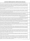 2
2 3
3NAR HIGH POWER ROCKETRY CERTIFICATION CHECKLIST
Has the rocket model that is being used for the certification attempt been built by the applicant requesting certification?
Is the nosecone or payload shoulder sufficiently light to prevent drag separation? The nosecone or payload should not
wobble side to side or separate from its own weight. Is a vent hole needed to relieve pressure for high altitude flight? Do
stage couplers fit snuggly to prevent bending or separation during flight? Is the body tube thickness adequate to withstand
high power flight (typically .050 inch walls or thicker)? Is there pre-existing damage which may weaken the model structure
(e.g. tube crimps)? Are screws and fasteners tight, if used?
Are the launch lugs securely fastened to the model? Verify no cracking of adhesive joints. Is the launch lug(s) appropriately
sized for the model, typically 1/4 inch or larger diameter? Will the launch lugs bind on the launch rod? Taped on launch
lugs are not permitted.
On cluster models are the spaces between the motor tubes filled to prevent ejection pressure leakage? If mixing black
powder and composite motors does the modeler assure composite motor ignition before black powder motor ignition
(composite motors ignite more slowly than black powder motors)? If the cluster model is not using all of its motors are the
unused motor tubes plugged to prevent ejection blow-by?
If a Level 1 Certification is being attempted, does the rocket model contain at least one single H or I impulse motor? If a
Level 2 Certification is being attempted, does the rocket model contain at least one single J, K or L impulse motor?
Is (are) the motor(s) sufficient to safely fly the model? Use motor manufacturer's recommendations or recommended motor
lists for similarly sized models as a starting point (Also consider, model weight, configuration, and finish when evaluating
motor capabilities). Is (are) the either NAR, Tripoli or CAR certified? Motors must be currently certified to be used.
o
Low current igniter?
Yes
N
Is (are) the rocket motor(s) firmly restrained in the model? Check for engine mount integrity to prevent a "fly through" (Is a
thrust ring used?). Check for a motor hook or similar motor restraint. Carefully check taped or friction fit motors for
tightness. Ask the modeler what adhesives were used during assembly. Are clusters wired in parallel?
If electronics are used, is the battery secured against "g" loads? Will electrical connections fail or loosen from acceleration
e
forces? Will ignit
rs stay fully inserted in rocket motors during boost? Is the user protected against inadvertent operation,
e.g. is the circuit remotely armed, are safety switches present, is an armed status indicator used (visual or audible)? Does
the modeler have a checklist or reminder to arm or operate the system prior to flight?
If radio control is used, is for flight functions (e.g. recovery) the operating frequency in the 27, 50, 53, or 72 megahertz
bands? Use of 75 megahertz for flight functions is not permitted. Is the antenna protected from breakage (not flopping
freely)? Did the operator range check his equipment?
Are the fins fully secured to the model? Check for looseness or cracking at the fin to body tube junction. "Thru the wall"
construction is recommended for high power models. Is the fin material compatible with the motor thrust range (1/8 inch
minimum plywood is recommended for high power models)? Ask the modeler how his fins are mounted, what adhesives
were used (epoxy is preferred), and what fin material was used. Are the fins mounted parallel to the roll axis of the model?
Are any warps present which may cause erratic flight?
Is the model stable? If stability is in doubt require proof of the CG and CP locations (remember CG should be forward of
the CP by approximately 1.0 body tube diameters). Ask the modeler to show the CG and CP locations and how they were
determined. Verify that the modeler shows the CG with the motor(s) intended for flight and not a smaller motor or fewer
motors (clusters). Ask the modeler to show CG and CP for the complete model and less each stage for a staged model.
Require evidence of CP calculations if further doubt exists.
Will the model "bust" the FAA waiver? Verify compliance by comparing model weight and power with charts/tables (if
available) or by calculation. Ask the modeler what the expected performance is and how he made his determination (e.g.
computer simulation, similar models).
Does the recovery system being used follow the requirements of an Active Recovery deployment system required for
certifying? Inspect the recovery system. Verify that the shock cord is not cut or frayed and free of burns. Are the shock
cord mounts securely mounted to the model? Are sharp edges present which may cut shock cords, parachute risers, and
suspension lines? Is hardware, e.g. swivels, screw eyes, sufficiently strong to withstand recovery loads. If required,
perform a pull test on the recovery system. Is parachute protection (e.g. wadding) adequate? Check for parachute
damage, e.g. tears, burns, which may spread during recovery.
Revision
2-Oct-2010, File
- hpappl
ADVERTISEMENT
0 votes
Related Articles
Related forms


Related Categories
Parent category: Business