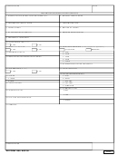
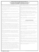
INSTRUCTIONS FOR COMPLETING DD FORM 1494,
"APPLICATION FOR EQUIPMENT FREQUENCY ALLOCATION"
TRANSMITTER EQUIPMENT CHARACTERISTICS PAGE
ITEM 1 - Nomenclature, Manufacturer’s Model No. Enter the
ITEM 13 - Maximum Bit Rate. Enter the maximum information bit
Government assigned alphanumeric equipment designation. If above is
rate for digital equipment, in bits per second. If spread spectrum is
not available, enter the manufacturer’s model number, e.g., MIT 502, and
used, enter the bit rate after encoding.
complete Item 2. If above is not available, enter a short descriptive title,
ITEM 14 - Modulation Techniques and Coding. Describe in detail
e.g., ATS-6 telemetry transmitter.
the modulation and/or coding techniques employed. For complex
ITEM 2 - Manufacturer’s Name. Enter the manufacturer’s name if
modulation schemes such as direct sequence spread spectrum,
available. If a manufacturer’s model number is listed in Item 1, this item
frequency hopping, frequency agile, etc., enter full details in Item 24,
must be completed.
"Remarks."
ITEM 3 - Transmitter Installation. List specific type(s) of vehicle(s),
ITEM 15 - Maximum Modulation Frequency. For frequency or
phase modulated transmitter enter the maximum modulation or
ship(s), plane(s) or building(s), etc., where the transmitter(s) will be
installed.
baseband frequency. This frequency is assumed to be the frequency
at -3 dB point on the high frequency side of the modulator response
ITEM 4 - Transmitter Type. Enter the generic class of the trans- mitter,
curve. Indicate the units, e.g., Hz, kHz or MHz.
e.g., Frequency Scan, Scan While Track Radar, Monopulse Tracker, AM
or FM Communications.
ITEM 16 - Pre-emphasis. For frequency or phase modulated
transmitters mark the appropriate block to indicate whether
pre-emphasis is available.
ITEM 5 - Tuning Range. Enter the frequency range through which the
transmitter is capable of being tuned, e.g., 225-400 MHz. For equipment
designed to operate only at a single frequency, enter this frequency.
ITEM 17 - Deviation Ratio. For frequency or phase modulated
Indicate units, e.g., kHz, MHz or GHz.
transmitter enter the deviation ratio computed with the formula:
ITEM 6 - Method of Tuning. Enter the method of tuning, e.g., crystal,
Deviation Ratio =
synthesizer or cavity. If the equipment is not readily tunable in the field,
Maximum Frequency Deviation
indicate in Item 24, "Remarks," the complexity of tuning. Include
Maximum Modulation Frequency
ITEM 18 - Pulse Characteristics. For pulse modulated transmitters:
complexity factors such as skill levels involved, major assemblies
involved, time required, and location (factory or depot) where equipment
is to be tuned.
a. Enter the pulse repetition rate in pulses per second (pps).
ITEM 7 - RF Channeling Capability. Describe the RF channeling
b. Enter the pulse width at the half voltage levels in microseconds
capability. For uniformly spaced channels, enter the center frequency of
(usec).
the first channel and channel spacing e.g., first channel 406 MHz, 100
c. Enter the pulse rise time in microseconds (usec). This is the time
kHz increments; for continuous tuning, enter the lowest frequency and
the word "continuous;" for others, such as SSB or cases where a
duration for the leading edge of the voltage pulse to rise from 10% to
channel selection is under software control, enter a detailed description
90% of its peak amplitude.
in Item 24, "Remarks." Any constraints on using any of these channels
must be described in Item 24, "Remarks," e.g., degraded channels,
d. Enter the pulse fall time in microseconds (usec). This is the time
internal hardwiring limitations or lockout capability for frequency hopping
duration for the trailing edge of the voltage pulse to fall from 90% to
10% of its peak amplitude.
systems.
ITEM 8 - Emission Designator(s). Enter the emission designator(s)
e. Enter the maximum pulse compression ratio, if applicable.
including the necessary bandwidth for each designator as described in
Chapter 9 of the NTIA Manual, e.g., 16K0F3E. For systems with a
ITEM 19 - Power. Enter the mean power delivered to the antenna
frequency hopping mode as well as a non-hopping mode enter the
terminals for all AM and FM emissions, or the peak envelope power
emission designators for each mode. Identify each mode as hopping or
(PEP) for all other classes of emissions. If there are any unique
non-hopping.
situations such as interrupted CW, provide details in Item 24,
"Remarks." Indicate the units, e.g., W or kW.
ITEM 9 - Frequency Tolerance. Enter the frequency tolerance, i.e., the
maximum departure of a transmitter from its assigned frequency after
ITEM 20 - Output Device. Enter a description of the device used in
normal warm-up time has been allowed. Indicate the units in parts per
the transmitter output stage, e.g., ceramic diode, reflex klystron,
million (ppm) for all emission types except single sideband which shall
transistor or TWT.
be indicated in Hertz (Hz).
ITEM 21 - Harmonic Level. Enter the harmonic level in dB relative
to the fundamental of the 2nd and 3rd harmonics. Enter in Item c. the
ITEM 10 - Filter Employed. Mark the appropriate block. Provide the
characteristics of any filter used in Item 24, "Remarks."
relative level in dB of the highest powered harmonic above the 3rd.
ITEM 11 - Spread Spectrum. Mark the appropriate block. If "Yes," see
ITEM 22 - Spurious Level. Enter the maximum value of spurious
instructions for Item 14.
emission in dB relative to the fundamental which occurs outside the
-60 dB point on the transmitter fundamental emission spectrum (Item
ITEM 12 - Emission Bandwidth. Enter the emission bandwidths for
12) and does not occur on a harmonic of the fundamental frequency.
which the transmitter is designed at the -3, -20, and -60 dB levels and
the occupied bandwidth. The bandwidth at -40 dB shall also be entered
ITEM 23 - FCC Type Acceptance No. Enter the FCC type
for pulse radar transmitters. The emission bandwidth is defined as that
acceptance number if applicable.
appearing at the antenna terminals and includes any significant
attenuation contributed by filtering in the output circuit or transmission
lines. Values of emission bandwidth specified should be indicated as
calculated or measured by marking the appropriate block. Indicate units
used, e.g., Hz, kHz or MHz. Note that the Occupied Bandwidth (Item
12.e.) is defined as the frequency bandwidth such that, below its lower
and above its upper frequency limits, the mean powers radiated are each
equal to 0.5% of the total mean power radiated.
DD FORM 1494, AUG 96
Transmitter Equipment Characteristics Page (Back)
 1
1 2
2


