Wire Sizes And Maximum Length Determination Chart Page 7
ADVERTISEMENT
 1
1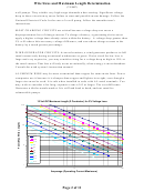 2
2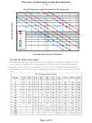 3
3 4
4 5
5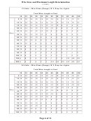 6
6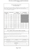 7
7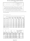 8
8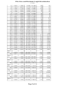 9
9 10
10 11
11Wire Sizes and Maximum Length Determination
(7/5/2007)
Universal Wire Sizing Chart
A 2-Step Process
This chart works for any voltage or voltage drop, American (AWG) or metric
(mm2) sizing. It applies to typical DC circuits and to some simple AC
circuits (single-phase AC with resistive loads, not motor loads, power factor
= 1.0, line reactance negligible).
Wire Size
Area mm2
COPPER
ALUMINUM
AWG
VDI
Ampacity
VDI
Ampacity
16
1.31
1
10
14
2.08
2
15
12
3.31
3
20
Not Recommended
10
5.26
5
30
8
8.37
8
55
6
13.3
12
75
4
21.1
20
95
2
33.6
31
130
20
100
0
53.5
49
170
31
132
00
67.4
62
195
39
150
000
85.0
78
225
49
175
0000
107
99
260
62
205
STEP 1: Calculate the Following:
VDI = (AMPS x FEET)/(%VOLT DROP x VOLTAGE)
VDI = Voltage Drop Index (a reference number based on resistance of wire)
FEET = ONE-WAY wiring distance (1 meter = 3.28 feet)
%VOLT DROP = Your choice of acceptable voltage drop (example: use 3 for 3%)
STEP 2: Determine Appropriate Wire Size from Chart
Compare your calculated VDI with the VDI in the chart to determine the
closest wire size. Amps must not exceed the AMPACITY indicated for the
wire size.
Metric Size
COPPER
ALUMINUM
by cross-sectional area
(VDI x 1.1 = mm2)
(VDI x 1.7 = mm2)
Available Sizes: 1 1.5 2.5 4 6 10 16 25 35 50 70 95 120 mm2
EXAMPLE:
20 Amp load at 24V over a distance of 100 feet with 3% max. voltage
drop
Page 7 of 11
ADVERTISEMENT
0 votes
Related Articles
Related forms


 Chord Chart")


Related Categories
Parent category: Life