Form Qpctmr - Quarterly Physical Connection Test & Maintenance Report September 2013 Page 2
Download a blank fillable Form Qpctmr - Quarterly Physical Connection Test & Maintenance Report September 2013 in PDF format just by clicking the "DOWNLOAD PDF" button.
Open the file in any PDF-viewing software. Adobe Reader or any alternative for Windows or MacOS are required to access and complete fillable content.
Complete Form Qpctmr - Quarterly Physical Connection Test & Maintenance Report September 2013 with your personal data - all interactive fields are highlighted in places where you should type, access drop-down lists or select multiple-choice options.
Some fillable PDF-files have the option of saving the completed form that contains your own data for later use or sending it out straight away.
ADVERTISEMENT
 1
1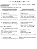 2
2Test Procedure for Backflow Preventer Valve Assembly
Set Up Procedure for Testing
1. Verify that upstream shut-off valve No. 1 is open, and there is water pressure. Close downstream shut-off valve No. 2. Note for
Reduced Pressure Zone Valves: A discharge from the relief port indicates a leaking No. 1 check valve. If there is no discharge No. 1
check can be assumed to be holding tight.
2. Flush test cocks Nos. 2, 3 & 4.
3. Close Test Kit high valve (A) and low valve (B), leave vent valve (C) open.
Reduced Pressure Zone Valve Assembly Test
Double Check Valve Assembly Test
A) Test the first check valve for tightness at a minimum of 5
A) Test the first check valve for a minimum of 1 PSID of static
PSID of static pressure:
pressure drop:
1.
Connect high-pressure hose to test cock #2.
1.
Connect high-pressure hose to test cock #2.
2.
Connect low-pressure hose to test cock #3.
2.
Connect low-pressure hose to test cock #3.
3.
Open test cocks #2 & #3.
3.
Open test cocks #2 & #3.
4.
Open test kit high valve (A) and bleed air and water
4.
Open test kit high valve (A) and bleed air and water
through vent hose… Close high valve (A).
through vent hose… Close high valve (A).
5.
Open test kit low valve (B) and bleed air and water through
5.
Open test kit low valve (B) and bleed air and water
vent hose… Close low valve (B) Slowly.
through vent hose… Close low valve (B) Slowly.
6.
Observe stable differential pressure on gauge and record on
6.
Observe stable differential pressure on gauge and record
test form. (Must be 5 PSID Minimum)
on test form. (Must be 1 PSID Minimum)
B) Test the second check valve for tightness against backpressure:
B) Test the second check valve for a minimum of 1 PSID static
1.
Connect vent hose to test cock #4.
pressure drop: (close test cocks #2 & #3 and remove high & low-
2.
Open test cock #4.
pressure hoses)
3.
Open test kit high valve (A)… Slowly.
1.
Connect high-pressure hose to test cock #3.
4.
Observe gauge and record on test form. Second check is
2.
Connect low-pressure hose to test cock #4.
tight if differential pressure drops slightly and holds steady.
3.
Open test cocks #3 & #4.
If pressure continues to drop until relief port discharges
4.
Open test kit high valve (A) and bleed air and water
second check is leaking.
through vent hose… Close high valve (A).
5.
Open test kit low valve (B) and bleed air and water
C) Test No. 2 shut-off valve for tightness:
through vent hose… Close low valve (B) Slowly.
1.
Close test cock #2.
6.
Observe stable differential pressure on gauge and record
2.
Observe gauge, if #2 shut-off valve is tight gauge will hold
on test form. (Must be 1 PSID Minimum)
steady, if leaking the differential pressure will fall. Record
result on form.
C) Test No. 2 shut-off valve for tightness:
Note: If No. 2 shut-off valve is leaking tests A & B are
1.
Repeat procedure for test A.
invalid; since the valve is not in a static condition. Another
2.
Connect vent hose to test cock #4.
shut-off valve downstream or a temporary by-pass from test
3.
Open test cock #4.
cock #1 to test cock #4 must be utilized.
4.
Open test kit high valve (A) Slowly.
5.
Close test cock #2.
D) Test the operation of the differential pressure relief valve:
6.
Observe gauge, if #2 shut-off valve is tight gauge will
Relief valve must open at a minimum of 2PSID below inlet.
hold steady, if leaking the differential pressure will fall.
1.
Open test cock #2, test kit high valve (A) shall remain open
Record result on form.
and close test kit vent valve (C).
Note: If No. 2 shut-off valve is leaking tests A & B are invalid;
2.
Slowly open the test kit low valve (B) until the differential
since the valve is not in a static condition. Another shut-off valve
pressure begins to fall… Slowly.
downstream or a temporary by-pass from test cock #1 to test cock
3.
Observe the relief valve port for the first discharge of water
#4 must be utilized.
and record the pressure differential on the gauge at this
point on the form.
ADVERTISEMENT
0 votes
Related Articles
Related forms


")


Related Categories
Parent category: Legal