Low Pass And High Pass Filter Circuits Page 3
ADVERTISEMENT
 1
1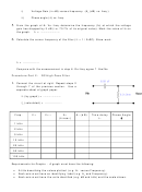 2
2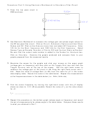 3
3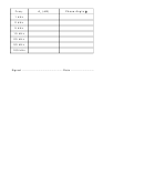 4
4Procedure: Part 3: Using Electronic Workbench to Simulate a Filter Circuit
Draw the low pass circuit in
1.
EWB as shown.
Use Electronic Workbench to measure the voltage gain and phase angle values for
2.
the RC low pass filter circuit. Click on Circuit, Schematic Options and then Show
Nodes and OK. Click on the Analysis menu item and select AC Frequency. Enter
100 Hz for the Start frequency and 1000 kHz for the End frequency. Select
Sweep Type as Decade, Number of Points 200 and Vertical Scale as Decibel.
Be sure that the output node number is added to the Nodes for Analysis box.
Click on Simulate.
Examine the graphs produced and compare them to your
graphs prepared from the measured results.
Maximize the screen for the graphs and click your mouse on the upper graph
3.
(voltage gain vs frequency) and then click on the Toggle Grid icon and then the
Toggle Cursors icon at the top of the screen.
Use the right hand cursor to
measure the voltage gain of the circuit in dB. Drag the right-hand cursor onto 1
kHz. Read the value of voltage Gain (in dB) from the value for y2 in the cursor
data display table. Record this value in the table below. Repeat this measurement
at the frequencies shown in the table below (i.e. 2kHz, 5kHz etc).
Find the corner frequency by moving the right-hand cursor until the y2 display
4.
shows as close to -3.01 dB as possible. Record the value of f
as the value shown
C
for x2.
f
= ______________
C
Repeat this procedure on the bottom graph (phase angle vs frequency) and record
5.
the set of measurements for phase angle in the table below. Compare these results
to what you obtained in Part 1.
ADVERTISEMENT
0 votes
Related Articles
Related forms


 Tax Deferral For Low-income And Low-income Senior Property Owners Application - Goverment Of The District Of Columbia
Legal
Tax Deferral For Low-income And Low-income Senior Property Owners Application - Goverment Of The District Of Columbia
Legal
 Supplemental Petition To Modify Parental Responsibility, Visitation, Or Parenting Plan/time-sharing Schedule And Other Relief - Florida Circuit Court
Legal
Supplemental Petition To Modify Parental Responsibility, Visitation, Or Parenting Plan/time-sharing Schedule And Other Relief - Florida Circuit Court
Legal

 Form 50-264 - Supplemental Application For Community Housing Development Organization Improving Property For Low-income And Moderate-income Housing Property Tax Exemption Previously Exempt In 2003
Financial
Form 50-264 - Supplemental Application For Community Housing Development Organization Improving Property For Low-income And Moderate-income Housing Property Tax Exemption Previously Exempt In 2003
Financial


Related Categories
Parent category: Miscellaneous