"Positive Displacement Reciprocating Pump Fundamentals - Power And Direct Acting Types" By Herbert H. Tackett, Jr., James A. Cripe, Gary Dyson Page 10
ADVERTISEMENT
 1
1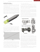 2
2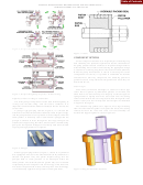 3
3 4
4 5
5 6
6 7
7 8
8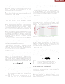 9
9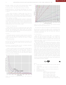 10
10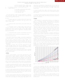 11
11 12
12 13
13 14
14Table of Contents
54
PROCEEDINGS OF THE TWENTY-FOURTH INTERNATIONAL PUMP USERS SYMPOSIUM • 2008
•
Piping vibration—Can result from improper piping support,
cavitation, or normal reciprocating pump hydraulic pulses
•
Noisy operation—Most present when pump is cavitating
•
Reduced capacity—Can result from fluid flashing. If it is, this is
an indication that the pumping chambers are filing up with gases
or vapors.
These factors contribute to reduced pump life, and are a
potential hazard to personnel and associated equipment. It is
possible to fracture a fluid cylinder and/or piping and damage the
pump drive end internals with high pressure surges occurring when
fluid is flashing or cavitating.
The following basic piping guidelines represent a combination
of Hydraulic Institute recommendations and criteria established by
experienced designers of systems containing reciprocating pumps.
While pump manufacturers cannot assume responsibility for the
piping system into which the pump is installed they can provide
valuable guidance that can aid system designs.
Figure 29. Flow Velocity in Suction Pipe Standard Weight
(Schedule 40) Steel Pipe Selection Curve.
Pump Suction Piping System
Piping should be laid out so no high points occur where vapor
The suction line velocity is based on an acceleration head of 0.7
pockets may form. Vapor pockets reduce the effective flow area of
feet per foot of suction line length and the acceleration head
the pipe and consequently make pump priming and operation
equation from the Hydraulic Institute Standard. For discharge line,
difficult. Vent any unavoidable high points and provide gauge and
a velocity not exceeding three times the suction line velocity is
drain connections adjacent to pump.
considered good practice.
Line Size
Acceleration Head
Many pump problems result from a suction line that is too small
After selecting the line size from above, it is necessary to
in diameter, or too long. Suction piping should be as follows to
calculate the total acceleration head (H
) in the suction line.
a
provide a smooth transition of fluid flow and result in reduced
As with centrifugal machines the NPSHA in the system must
piping friction losses:
always exceed pump NPSHR plus piping friction losses, but with
Be short and direct
reciprocating pumps a further consideration must be made with
respect to acceleration head.
•
Be one to two sizes larger than pump suction connection. Use
Fluid inside the pump is accelerated and decelerated as a result of
eccentric type pipe reducers at pump with flat side up to avoid a
the reciprocating motion and suction valves opening and closing.
possible vapor pocket.
This accelerated and decelerated pulsation phenomenon is also man-
•
Contain a minimum number of turns. Accomplish necessary
ifested within the suction pipe. The energy required to keep the fluid
turns with long radius elbows or laterals.
in the suction pipe from falling below vapor pressure is called accel-
eration head. The key influencing factors of the pump are pump
Figure 28 contains a chart to aid in the design of suction piping.
speed, plunger size, valve spring load and spring rate, valve lift, valve
From this figure determine the optimum suction velocity for
passage area, cylinder passage configuration, suction manifold con-
the appropriate machine and use this information in Figure 29
figuration, and power end connecting rod center to center of bearing
to determine the appropriate pipe size. This pipe sizing chart is
distance to throw radius ratio. While the key influencing factors for
based on Schedule 40 piping and the values should be adjusted
the suction piping are actual suction pipe length, mean flow velocity
accordingly for heavier schedules.
in suction line, and fluid being pumped. If sufficient energy is not
available, problems such as fluid flashing, cavitation, piping
vibration, noisy operation, reduced capacity, and reduced pump life
can occur. To calculate the H
required to overcome this phenomenon,
a
use the following empirical equation:
where:
H
= Head in feet (meters) of liquid pumped to produce required
a
acceleration
L
= Actual suction pipe length in feet (meters) not equivalent
length
V
= Mean flow velocity in suction line in feet per second (m/s)
N
= Pump speed in rpm
C
= Pump constant factor of…
0.200 for simplex double acting
0.200 for duplex single acting
0.400 for simplex single acting
0.115 for duplex double acting
Figure 28. Maximum Recommended Suction Line Velocity for
0.066 for triplex single or double acting
Pump Type.
0.040 for quintuplex single or double acting
ADVERTISEMENT
0 votes
Related Articles
Related forms
 By John H Hopkins Jr. Sheet Music")
 By John H Hopkins Jr. Sheet Music")
 By John H Hopkins Jr. Sheet Music")

 Designation Of Patient Advocate Form And Directions For Durable Power Of Attorney For Health Care Form
Medical
Designation Of Patient Advocate Form And Directions For Durable Power Of Attorney For Health Care Form
Medical
 Form 232 - Power Of Attorney By Individual For The Collection Of A Specified Check Drawn On The United States Treasury - 1975
Legal
Form 232 - Power Of Attorney By Individual For The Collection Of A Specified Check Drawn On The United States Treasury - 1975
Legal

 Form R-1012 - Application For Exemption And Direct Payment Authorization For A Call Center As Defined Under Louisiana Revised Statute - Sales Tax Division Of Department Of Revenue Of State Of Louisiana
Financial
Form R-1012 - Application For Exemption And Direct Payment Authorization For A Call Center As Defined Under Louisiana Revised Statute - Sales Tax Division Of Department Of Revenue Of State Of Louisiana
Financial


Related Categories
Parent category: Business