"Positive Displacement Reciprocating Pump Fundamentals - Power And Direct Acting Types" By Herbert H. Tackett, Jr., James A. Cripe, Gary Dyson Page 9
ADVERTISEMENT
 1
1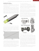 2
2 3
3 4
4 5
5 6
6 7
7 8
8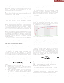 9
9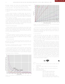 10
10 11
11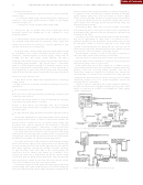 12
12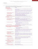 13
13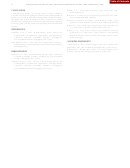 14
14Table of Contents
POSITIVE DISPLACEMENT RECIPROCATING PUMP FUNDAMENTALS—
53
POWER AND DIRECT ACTING TYPES
design is required to make allowance for thermal growth to
vary between 1 to 5 percent based upon pump speed and
valve design. In general, most pump designs will
maintain good alignment between the pumping element and
stuffing box seal.
typically have a 3 percent loss.
•
Any pump speed limits imposed by user specifications—This is
Mechanical Efficiency
needed to determine the pump plunger/piston size, and actual
The mechanical efficiency (ME) of a reciprocating machine,
pump speed to comply for the application.
as previously mentioned, is an important consideration. This
•
Fluid specific gravity—This is used in determining the pump
section outlines the influencing factors with respect to mechanical
plunger/piston size, pump speed, and what modifications may be
efficiency and illustrates both power and direct acting pumps.
required for a low enough NPSHR.
Power Pumps
•
Fluid compressibility factor or bulk modulus at pumping
temperatures—This is used to determine the pump volumetric
As shown in Figure 27, mechanical efficiency varies as a
function of frame load, which is simply the pressure applied times
efficiency and in turn pump speed for a given plunger/piston size
the cross-sectional area of the plunger/piston. Percentage of frame
within a fluid end.
load is actual frame load from the application divided by the frame
•
Fluid vapor pressure at pumping temperatures—Needed to
load rating established by the pump vendor. Higher frame loading
determine pump plunger/piston size, pump speed, and any
increases ME. Therefore, the plunger/piston should be sized to
modifications required for low enough NPSHR.
provide as high as possible frame load within the pump’s frame
•
Fluid viscosity at pumping temperatures—Allows determination
load rating to achieve the highest possible ME.
of pump plunger/piston size, pump speed. Starting at 300 SSU
(~72 cP) pump speed needs to be reduced as indicated in API-674
(1995) Second Edition Figure 1 and ANSI/HI 6.1-6.5 (1994). Also,
helps to determine what or if modifications may be required for
low enough NPSHR.
•
Does fluid contain any substances or chemicals that will cause
corrosion and/or erosion within the pump selected?—This aids in
determining the pump fluid end size, pump speed, pump valve type
and size, stuffing box seal design (as required for personnel and/or
environment protection), and other modifications needed to
Figure 27. Mechanical Efficiency Versus Frame Load.
provide low NPSHR.
As shown in the above, having all of this important information
helps determine key aspects of the pump selected and used, in
Power pumps have mechanical efficiencies up to 87 percent with
addition to many important pump performance and construction
sleeve type power end bearing pumps, and up to 90 percent for
characteristics, including materials of construction, stuffing box
roller type power end bearing pumps. Contributing to the losses are
seal type, and fluid end design.
the pump bearings, stuffing box seals, and the pump valves.
Additional losses from drive components (i.e., driver, belts, gears,
RECIPROCATING PUMP EFFICIENCY
couplings, etc.) should be determined and accounted for in the
While centrifugal pump efficiency is understood in terms of
overall efficiency of the complete pump unit.
leakage, mechanical, and hydraulic losses, the efficiency of a
Direct Acting Pumps
reciprocating machine is somewhat different. The main constituents
of reciprocating pump efficiency are covered below.
Mechanical efficiency or pump efficiency is a ratio of force
applied to the fluid pumped by the piston/plunger by the force
Volumetric Efficiency
transmitted by the drive piston from the drive media (steam, gas, or
As shown in the following equation reciprocating pump
air), minus losses due to friction from drive piston drag, stuffing
volumetric efficiency (VE) can be determined with reasonable
box packing, and pump valves. This ratio is based upon differential
accuracy (within 1 percent), if all factors are known. Also evident is that
pressures at both the pump’s drive and fluid ends, as determined
VE is dependant upon the fluid compressibility, application pressure,
using the following equation.
pump C/D ratio (pumping chamber clearance to displacement ratio),
and pump valve slip. Therefore, since fluid compressibility, pump C/D
ratio, and pump valve slip are known by fluid properties and pump
dimensions and characteristics, the actual fixed displaced volume per
where:
complete cycle (rpm) is dependant upon pressure and not pump speed.
A
= Cross-sectional area of fluid piston/plunger
L
p
= Differential pressure across the pump fluid end
L
A
= Cross-sectional area of fluid piston/plunger
DR
p
= Differential pressure across the pump drive end
where:
DR
P
= Differential pressure (psig) = P
P
D
S
PUMP AND SYSTEM INTERACTION
= Compressibility factor of fluid to be pumped at pumping
temperature reciprocal (inverse) of fluid bulk modulus at
One significant factor in the successful operation of any pump is
pumping temperature
an appropriately designed piping system. A poorly designed system
= Ratio of total volume between the suction and discharge
can cause problems such as:
valves inside the pumping chamber when the plunger
•
Fluid flashing—Entrained gases in the fluid coming out when
(or piston) is at full forward stroke divided by the plunger
pressure in piping or pump falls below fluid vapor pressure
(or piston) displacement volume (area × stroke length); also
•
called C/D ratio
Cavitation—Free gases in a fluid being forced back into the
V
= Valve loss or VE loss from fluid slippage back past the
fluid. These implosions cause severe pressure spikes that pit and
L
pump valves before they can close and seal. This will
damage pump internal parts.
ADVERTISEMENT
0 votes
Related Articles
Related forms
 By John H Hopkins Jr. Sheet Music")
 By John H Hopkins Jr. Sheet Music")
 By John H Hopkins Jr. Sheet Music")

 Designation Of Patient Advocate Form And Directions For Durable Power Of Attorney For Health Care Form
Medical
Designation Of Patient Advocate Form And Directions For Durable Power Of Attorney For Health Care Form
Medical
 Form 232 - Power Of Attorney By Individual For The Collection Of A Specified Check Drawn On The United States Treasury - 1975
Legal
Form 232 - Power Of Attorney By Individual For The Collection Of A Specified Check Drawn On The United States Treasury - 1975
Legal

 Form R-1012 - Application For Exemption And Direct Payment Authorization For A Call Center As Defined Under Louisiana Revised Statute - Sales Tax Division Of Department Of Revenue Of State Of Louisiana
Financial
Form R-1012 - Application For Exemption And Direct Payment Authorization For A Call Center As Defined Under Louisiana Revised Statute - Sales Tax Division Of Department Of Revenue Of State Of Louisiana
Financial


Related Categories
Parent category: Business