Control System Design Project 4: Control Design Via Frequency Response
ADVERTISEMENT
Control System Design
Project 4: Control Design Via Frequency Response
Name: _____________________________________________________________________ Date: __________________________
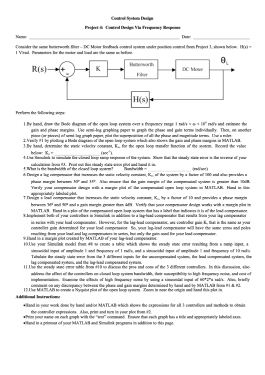
Consider the same butterworth filter – DC Motor feedback control system under position control from Project 3, shown below. H(s) =
1 V/rad. Parameters for the motor and load are the same as before.
Perform the following steps:
4
1. By hand, draw the Bode diagram of the open loop system over a frequency range 1 rad/s < ω < 10
rad/s and estimate the
gain and phase margins. Use semi-log graphing paper to graph the phase and gain terms individually. Then, on another
piece (or pieces) of semi-log graph paper, plot the superposition of all the phase and magnitude terms. Use a ruler.
2. Verify #1 by plotting a Bode diagram of the open loop system which also shows the gain and phase margins in MATLAB.
3. By hand, determine the static velocity constant, K
, for the open loop transfer function of the system. Record the value
v
-1
below: K
= _____________________ (sec
).
v
4. Use Simulink to simulate the closed loop ramp response of the system. Show that the steady state error is the inverse of your
calculation from #3. Print out this steady state error plot and hand it in.
5. What is the bandwidth of the closed loop system?
Bandwidth = ____________________ (rad/sec)
6. Design a lag compensator that increases the static velocity constant, K
, of the system by a factor of 100 and also provides a
v
phase margin between 50⁰ and 55⁰. Also ensure that the gain margin of the compensated system is greater than 10dB.
Verify your compensator design with a margin plot of the compensated open loop system in MATLAB. Hand in this
appropriately labeled plot.
7. Design a lead compensator that increases the static velocity constant, K
, by a factor of 10 and provides a phase margin
v
between 36⁰ and 50⁰ and a gain margin greater than 4dB. Verify that your compensator design works with a margin plot in
MATLAB. Hand in a plot of the compensated open loop system that has a label that indicates it is of the lead compensator.
8. Implement both of your controllers in Simulink in addition to a lag-lead compensator that results from your lag compensator
in series with your lead compensator. However, for the lag-lead compensator, use controller gain K
that is the same as your
c
controller gain determined for your lead compensator. So, your lag-lead compensator will have the same zeros and poles
resulting from your lead and lag compensators in series, but only the gain used for your lead compensator.
9. Hand in a margin plot created by MATLAB of your lag-lead compensator.
10. Use your Simulink model from #8 to create a table which shows the steady state error resulting from a ramp input, a
sinusoidal input of amplitude 1 and frequency of 1 rad/s, and a sinusoidal input of amplitude 1 and frequency of 10 rad/s.
Tabulate the steady state error from the 3 different inputs for the uncompensated system, the lead compensated system, the
lag compensated system, and the lag-lead compensated system.
11. Use the steady state error table from #10 to discuss the pros and cons of the 3 different controllers. In this discussion, also
address the affect of the controllers on closed loop system bandwidth, their susceptibility to high frequency noise, and cost of
implementation. Examine the effects of high frequency noise by using a sinusoidal input of 60*2*π rad/s. Also, briefly
comment on any discrepancy between the phase and gain margins determined by hand and by MATLAB from #1 & #2.
12. Use MATLAB to create a Nyquist plot of the open loop system. Zoom in near the origin and hand this plot in.
Additional Instructions:
•
Hand in your work done by hand and/or MATLAB which shows the expressions for all 3 controllers and methods to obtain
the controller expressions. Also, print and turn in your plot from #2.
•
Print your name on each graph with the “text” command. Ensure that each graph has a title and appropriately labeled axes.
•
Hand in a printout of your MATLAB and Simulink programs in addition to this page.
ADVERTISEMENT
0 votes
Related Articles
Related forms
Related Categories
Parent category: Education
 1
1


