Sample Design Calculations Page 22
ADVERTISEMENT
 1
1 2
2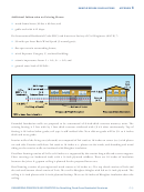 3
3 4
4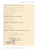 5
5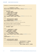 6
6 7
7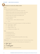 8
8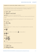 9
9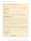 10
10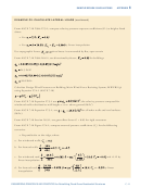 11
11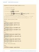 12
12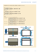 13
13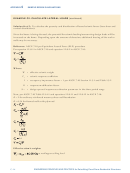 14
14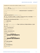 15
15 16
16 17
17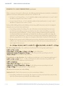 18
18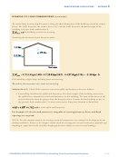 19
19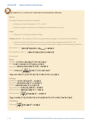 20
20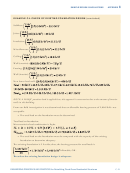 21
21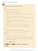 22
22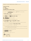 23
23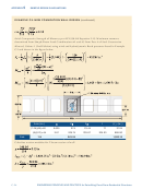 24
24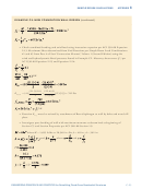 25
25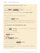 26
26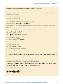 27
27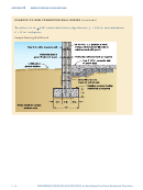 28
28 29
29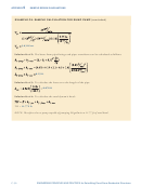 30
30 31
31 32
32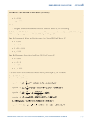 33
33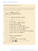 34
34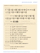 35
35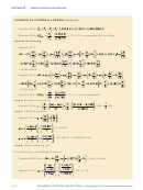 36
36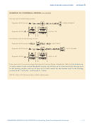 37
37C
APPENDIX
SAMPLE DESIGN CALCULATIONS
EXAMPLE C5. NEW FOUNDATION WALL DESIGN
Given:
Per original Sample Calculation Statement:
• Solutions to above Examples C1, C2, C3, and C4
• Assume seismic load condition controls design
• Field investigation information and additional information on-site as noted in previous
sections
• Assume #4 reinforcing bars at 48 in. o.c. in solid grouted cores
• G =0.4E where E = modulus of elasticity per American Concrete Institute (ACI) 530-08
Section 1.8.2.2
• Assume compressive strength of masonry, f '
= 2,000 lb/in.
2
m
• Type M or S mortar per ACI 530-08 Section 1.8.2.2 E
= 900 f '
= 900 (2,000)
m
m
= 1.8 x 10
lb/in.
6
2
• With #4 @ 48 in. o.c. the equivalent solid thickness is 4.6 in. = 0.38 ft
• M = 120 kips-ft from Example C2 (maximum moment split in half due to 2 walls)
• V = 19.2 kips from Example C2 (maximum shear split in half due to 2 walls)
Find:
1. Design the foundation wall and connection to the footing
2. Design top of wall connection. (Checking anchor bolts for pullout from masonry
Solution for #1: To design the foundation wall connection to the footing:
New Wall Design:
• Minimum wall reinforcement is #4 @ 48 in. A
= 0.20/48 in.
s
• Next determine V
(shear strength provided by masonry) per ACI 530-08 Equation 3-22
m
• Moment is calculated from Seismic Lateral Forces. Refer to the figure below for indicated
forces with associated moment arms.
M
=
−
+
V
4.0 1.75
A
f ’
0.25
P
m
n
m
Vd
C-22
ENGINEERING PRINCIPLES AND PRACTICES for Retrofitting Flood-Prone Residential Structures
ADVERTISEMENT
0 votes
Related Articles
Related forms


")


Related Categories
Parent category: Business