Aircraft Accident Brief Ntsb/aab-02/01 (Pb2002-910401): Egypt Air Flight 990, Boeing 767-366er, Su-Gap - National Transportation Safety Board Page 15
ADVERTISEMENT
: Egypt Air Flight 990, Boeing 767-366er, Su-Gap - National Transportation Safety Board Printable pdf") 1
1  2
2  3
3  4
4  5
5  6
6  7
7  8
8  9
9  10
10  11
11  12
12  13
13  14
14  15
15 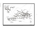 16
16 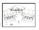 17
17  18
18  19
19  20
20  21
21  22
22  23
23  24
24  25
25  26
26  27
27  28
28  29
29  30
30  31
31  32
32  33
33  34
34  35
35  36
36  37
37  38
38 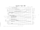 39
39  40
40  41
41  42
42  43
43  44
44  45
45 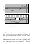 46
46  47
47  48
48  49
49  50
50  51
51  52
52  53
53  54
54  55
55  56
56  57
57  58
58  59
59  60
60  61
61  62
62  63
63  64
64  65
65  66
66  67
67  68
68  69
69  70
70  71
71  72
72  73
73  74
74  75
75  76
76  77
77  78
78  79
79  80
80  81
81  82
82  83
83  84
84  85
85  86
86  87
87  88
88  89
89  90
90  91
91  92
92  93
93  94
94  95
95  96
96  97
97  98
98  99
99  100
100  101
101  102
102  103
103  104
104  105
105  106
106  107
107  108
108  109
109  110
110  111
111  112
112  113
113  114
114  115
115  116
116  117
117  118
118  119
119  120
120  121
121  122
122  123
123  124
124  125
125  126
126  127
127  128
128  129
129  130
130  131
131  132
132  133
133  134
134  135
135  136
136  137
137  138
138  139
139  140
140  141
141  142
142  143
143  144
144  145
145  146
146  147
147  148
148  149
149  150
150  151
151  152
152  153
153  154
154  155
155  156
156  157
157  158
158  159
159  160
160 9
configured to seat a maximum of 10 first-class, 22 business-class, and 185 economy-class
passengers and to carry cargo.
The accident airplane was equipped with two P&W 4060 turbofan engines.
Company maintenance records indicated that the No. 1 (left) engine, S/N 724126, was
installed on the accident airplane on April 19, 1998, and had operated about 25,708 hours
since new and that the No. 2 (right) engine, S/N 724127, was installed on the accident
airplane on June 3, 1998, and had operated about 19,316 hours since new.
767 Longitudinal Control System Information
Because the accident sequence involved a sustained unusual motion about the
airplane’s pitch axis, the Safety Board examined the 767’s longitudinal flight control
system. According to the Boeing 767 Maintenance Manual, the 767’s longitudinal flight
control system includes two (left and right) sets of linked elevator surfaces (inboard and
outboard), which are attached to the rear spar of the movable horizontal stabilizer by
hinges. Each outboard elevator surface is driven by three power control actuators (PCA).
Because the outboard and inboard surfaces are linked, the inboard elevator surfaces move
when the outboard elevator surfaces are driven. Hydraulic power for elevator PCA
movement is provided by the 767’s three independent hydraulic systems—each hydraulic
system powers one of each elevator surface’s PCAs, which provides redundancy within
the elevator control system. (Components in the elevator control system are shown in
figures 1a and 1b.)
Two parallel sets (one operated from the captain’s side, the other from the first
officer’s side) of flight control components move the elevator surfaces. Control column
inputs made at the captain’s position are linked directly to the actuators for the left
elevator surface, whereas control column inputs made at the first officer’s position are
linked directly to the actuators for the right elevator surfaces. The two parallel sets of
flight control components are linked together at the forward and aft override
mechanisms/linkages and slave cable interconnects. Flight control commands from the
29
captain’s and first officer’s control columns are transmitted through linkages and cables
from the front of the airplane to the left and right aft quadrant assemblies, respectively.
The aft quadrant assemblies then translate the inputs to the respective bellcrank
assemblies and the input control rods for each of the three elevator PCAs for each
outboard elevator surface.
28
A flight cycle is one complete takeoff and landing sequence.
29
The cables for the captain’s (left-side) system are routed below the floor boards, and the cables for the
first officer’s (right-side) system are routed above the cabin ceiling.
NTSB/AAB-02/01
ADVERTISEMENT
0 votes
Related Articles
Related forms
 Investigation Party Form")


 During An Allegiant Air Flight")


Related Categories
Parent category: Legal